![]() ----------- Your trusted
source for independent sensor data- Photons to Photos------------ Last revised:
2020-06-05 14:00 GMT-5
----------- Your trusted
source for independent sensor data- Photons to Photos------------ Last revised:
2020-06-05 14:00 GMT-5
Previous Article----------------------------------- Table of Contents------------------------------------ Next Article
--------------------------------- Optics Primer - Depth of Field
--------------------------------------------------------- By Bill Claff
When light rays pass through a
lens we imagine that perfectly focused rays converge at a point on the Image
Plane.
For a number of reasons this is never true in practice.
In the discussion that follows I'll use US patent 6,549,343 Example 1 which is
a 94mm f/1.8 lens with a 43.28mm image circle.
I won't the topic of the Circle of Confusion (CoC) here but will use a CoC
value of 43.28mm / 1500 or approximately 0.029mm.
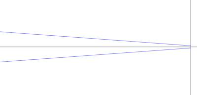
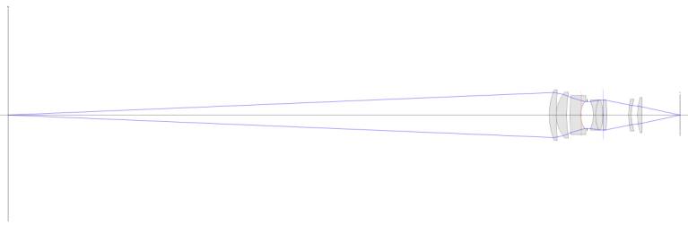
Here we see on-axis and off-axis
ray bundles at f/1.8 for a subject that is approximately 700mm from the Image
Plane:
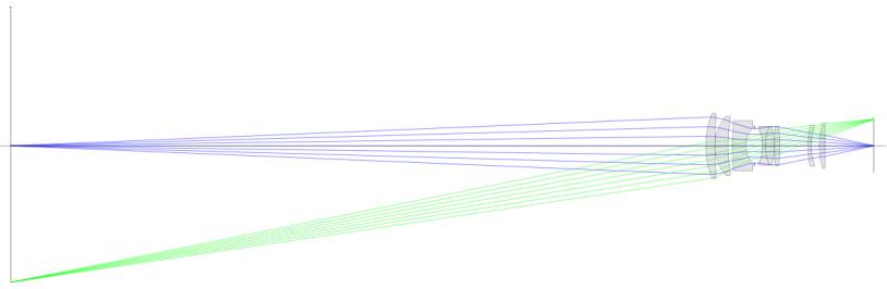
Let's look more closely at the Image Plane
: 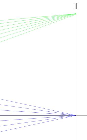
This looks pretty good. Note the obvious fact that rays off the optical axis
arrive in an asymmetrical bundle and that if focus is not perfect this will
form an ellipse on the Image Plane as opposed to the on-axis bundle which will
form a circle.
Despite this, as well as the fact that curvature of field and other
imperfections will affect focus off the optical axis; we will disregard
off-axis rays going forward.
Here's an extreme view of the on-axis ray bundle:
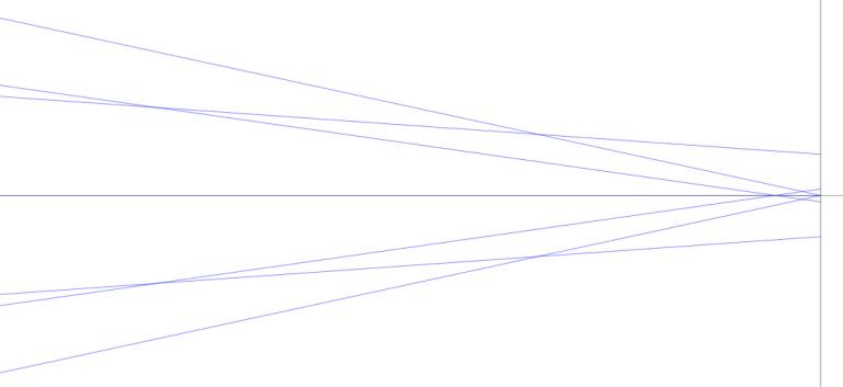
Now we see that spherical and other aberrations make the rays not arrive
perfectly at a point.
In this extreme enlargement the rays furthest off-axis form a circle with a
diameter of about 0.0166mm; well below our CoC of 0.029mm.
Going forward we'll only concern ourselves with the rays that pass by the edge
of the aperture stop, the on-axis marginal rays.
Here are the on-axis marginal
rays at a f/1.8 and f/5.6:
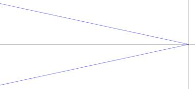
At this extreme enlargement we
see a slight shift of focus at f/5.6 which we will disregard.
The key point is that the cone of rays arrive more perpendicular at the higher
f-number.
If the image plane were moved slightly, left for example; the cone would be
truncated to a circle rather than arriving at a point.
This is Depth of Focus which is not the same as Depth of Field but is closely
related.
Depth of Field arises from
moving the Object Plane (subject distance) rather than the Image Plane.
For example here are rays for f/1.8 arriving at the image plane under the CoC
0.029mm condition:
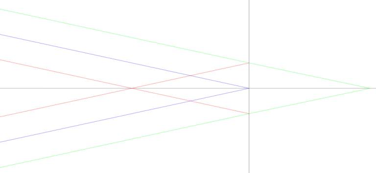
Where blue is in perfect focus, red is the far DoF limit and green is the near
DoF limit.
Note that the red and green intersect the Image Plane at the CoC diameter.
The rays leaving from the object
side look like this:
The red vertex is 702.03mm from the Image Plane, the blue is 700.21mm, and the
green is 698.40mm.
This close to the subject DoF is almost evenly distributed before and after the
subject.
At longer distances we'll discover there is more depth behind the subject than
in front. In this case 1.82mm behind and 1.81mm in front.
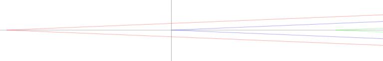
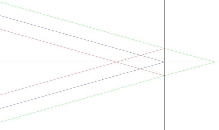
Here are rays from a more
distant subject (still at f/1.8):
 Image
Plane
Image
Plane
![]() Object
Plane
Object
Plane
In this case the vertex distances are 5059mm, 4920mm, and 4789mm; 139mm behind,
131mm in front, for a total of 270mm.
Let's examine the geometry of
this system using the 700mm f/1.8 subject distance as an example:
And a bit closer for clarity:
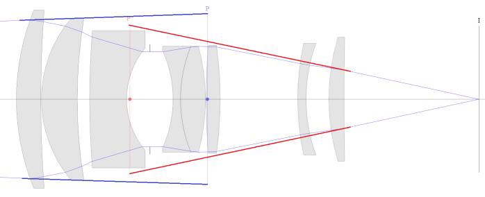
I have annotated this drawing.
Note that the angle of the incoming rays is controlled by the diameter of the
entrance pupil (P in blue).
And that the angle of the projected rays is controlled by the diameter of the
exit pupil (P' in red).
Since the rays incident on the Image Plane control Depth of Field it is exit
pupil that matters.
Almost everywhere (else) you will read that the entrance pupil controls Depth
of Field but strictly speaking that isn't so.
The ratio of the diameter of the
exit pupil to that of the entrance pupil is called pupil magnification;
typically indicated by the letter P.
In the case of this lens pupil magnification (P) is 0.85.
At infinity focus the line that
connects the edge of the exit pupil to the Image Plane at the optical axis
extends to the rear principal plane at the same height as the entrance pupil.
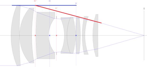
This simplification eliminates
pupil magnification and makes it appear that the entrance pupil controls Depth
of Field.
However, this is only true at infinity focus and pupil magnification becomes
more and more important as we increase magnification.
Here are the geometric elements
we need to compute Depth of Field:
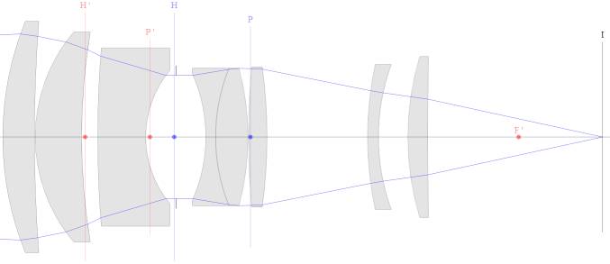
The height of the exit pupil (P'
in red) is (pupil magnification) * (entrance pupil height).
The distance along the optical axis between exit pupil and the rear focal point
(F' in red) is (pupil magnification) * (focal length).
And the distance between the rear focal point and the Image Plane (I in black)
is (focal length) * magnification.
Finally, we'll eventually need the (signed) distance from the front (H in blue)
to the rear (H' in red) principal planes.
We put this in the context of a
simplified version of our earlier result:
So we need to know where the red and green lines cross the x-axis when the also
cross the y-axis at minus and plus the CoC radius respectively.
After judicious use of similar triangles and some (actually, a lot) of algebra we have:
mn = ( m + C / PD) / (1 - C / P'D) near magnification
mf = ( m - C / PD) / (1 + C / P'D) far magnification
Where m is magnification at focus, C is CoC, PD is entrance pupil diameter, and P'D is exit pupil diameter.
Note that m for mf must be greater than or equal to:
mh = C / PD hyper-focal magnification
Otherwise far magnification goes beyond infinity.
Note also that if P'D drops to C then near magnification goes to infinity; a pin-hole camera with infinity DoF.
So, where is subject distance? And where is focal length? Before we go there let's consider where we are.
These equations show us that DoF
is really about magnification.
Subject distance will depend on the focal length of the lens you're using but
DoF itself comes down to magnification.
When you're in the field; is it easier to judge the size of your subject or
your distance to your subject?
I encourage you to think about how you can incorporate magnification thinking
rather than distance thinking into your DoF strategy.
As for subject distance; we know that subject distance:
S = ( 1 / m + 1 ) * f + i + ( 1 + m ) * f subject distance
Where m is magnification, f is focal length, and i is the inter-nodal distance (signed distance between the front and rear principal planes).
There are many ways to rework this equation a common form is:
S = ( 1 + m ) ^ 2 / m * f + i
The distance values given above
were from Optical Bench ray tracing. Let's see how they check out against the
formulas.
C = 0.029mm
m = 0.01991mm
PD = 52.45145mm
P'D = 44.23296mm
f = 94.43858mm
i = -13.08443mm
mh = 0.029mm / 52.45145mm = 0.000553
S = ( 1 + 0.000553 ) ^
2 / 0.000553 * 94.43858mm + -13.08443mm = 170,984mm
mn = (0.01991 + 0.029mm / 52.45145mm) /
(1 - 0.029mm / 44.23296mm) = 0.020476
S = ( 1 + 0.020476) ^
2 / 0.020476 * 94.43858mm + -13.08443mm = 4790mm (~= 4789mm)
mf = (0.01991 - 0.029mm / 52.45145mm) /
(1 + 0.029mm / 44.23296mm) = 0.019344
S = ( 1 + 0.019344) ^
2 / 0.019344 * 94.43858mm + -13.08443mm = 5060mm (~=5059mm)
Previous Article----------------------------------- Table of Contents------------------------------------ Next Article