Constructing a Spectral Locus
Prepared 2014-04-20 by Bill Claff
I find it helpful to visualize a Spectral Locus on a CIE
1931 style chart.
If spectral sensitivity data in a tabular form are not available then the first
step is to gather such information from any published spectral sensitivity
chart.
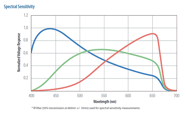
In locating such a chart it's important that an IR cut or other filter is
included rather than just showing the sensitivity of the bare sensor.
For the Foveon X3 this is the chart I started with:
Somehow you need to read the values off of the chart for each of the channels.
I use a technique with Microsoft Excel to accomplish this.
I create a scatter chart overlaying the spectral sensitivity chart and adjust
values until I have the proper fit.
For example:
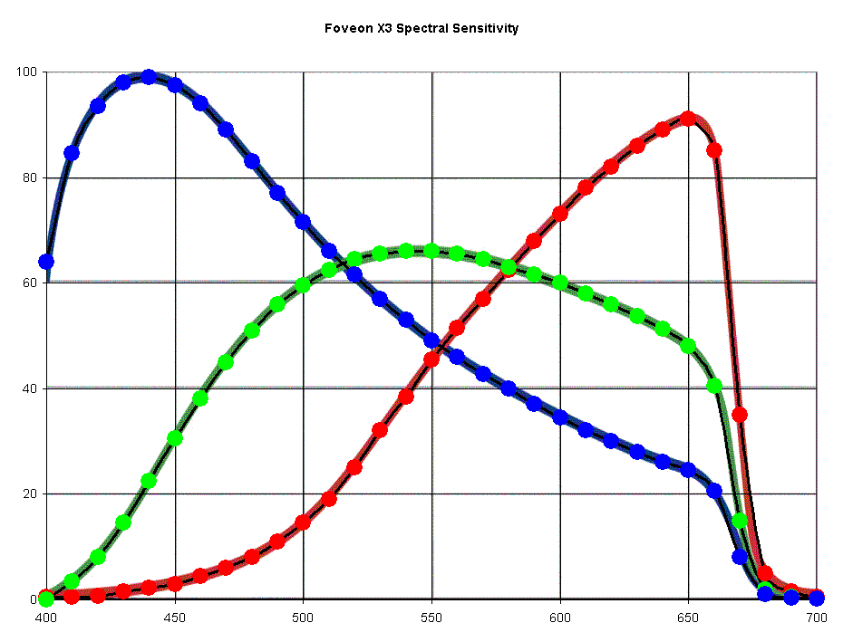
The colored circles on the chart represent the data points being read off of
the curves on the background image.
In the following table these are the CIE X, CIE Y, and CIE Z columns:
|
nm |
CIE X |
CIE Y |
CIE Z |
CIE x |
CIE y |
CIE z |
|
400 |
0.5 |
0 |
64 |
0.007752 |
0.000000 |
0.992248 |
|
410 |
0.5 |
3.5 |
84.5 |
0.005650 |
0.039548 |
0.954802 |
|
420 |
0.75 |
8 |
93.5 |
0.007335 |
0.078240 |
0.914425 |
|
430 |
1.5 |
14.5 |
98 |
0.013158 |
0.127193 |
0.859649 |
|
440 |
2.25 |
22.5 |
99 |
0.018182 |
0.181818 |
0.800000 |
|
450 |
3 |
30.5 |
97.5 |
0.022901 |
0.232824 |
0.744275 |
|
460 |
4.5 |
38 |
94 |
0.032967 |
0.278388 |
0.688645 |
|
470 |
6 |
45 |
89 |
0.042857 |
0.321429 |
0.635714 |
|
480 |
8 |
51 |
83 |
0.056338 |
0.359155 |
0.584507 |
|
490 |
11 |
56 |
77 |
0.076389 |
0.388889 |
0.534722 |
|
500 |
14.5 |
59.5 |
71.5 |
0.099656 |
0.408935 |
0.491409 |
|
510 |
19 |
62.5 |
66 |
0.128814 |
0.423729 |
0.447458 |
|
520 |
25 |
64.5 |
61.5 |
0.165563 |
0.427152 |
0.407285 |
|
530 |
32 |
65.5 |
57 |
0.207120 |
0.423948 |
0.368932 |
|
540 |
38.5 |
66 |
53 |
0.244444 |
0.419048 |
0.336508 |
|
550 |
45.5 |
66 |
49 |
0.283489 |
0.411215 |
0.305296 |
|
560 |
51.5 |
65.5 |
46 |
0.315951 |
0.401840 |
0.282209 |
|
570 |
57 |
64.5 |
42.75 |
0.347032 |
0.392694 |
0.260274 |
|
580 |
62.5 |
63 |
40 |
0.377644 |
0.380665 |
0.241692 |
|
590 |
68 |
61.5 |
37 |
0.408408 |
0.369369 |
0.222222 |
|
600 |
73 |
60 |
34.5 |
0.435821 |
0.358209 |
0.205970 |
|
610 |
78 |
58 |
32 |
0.464286 |
0.345238 |
0.190476 |
|
620 |
82 |
56 |
30 |
0.488095 |
0.333333 |
0.178571 |
|
630 |
86 |
53.75 |
28 |
0.512668 |
0.320417 |
0.166915 |
|
640 |
89 |
51.25 |
26 |
0.535338 |
0.308271 |
0.156391 |
|
650 |
91 |
48 |
24.5 |
0.556575 |
0.293578 |
0.149847 |
|
660 |
85 |
40.5 |
20.5 |
0.582192 |
0.277397 |
0.140411 |
|
670 |
35 |
15 |
8 |
0.603448 |
0.258621 |
0.137931 |
|
680 |
5 |
1.9 |
1.1 |
0.625000 |
0.237500 |
0.137500 |
|
690 |
1.5 |
0.5 |
0.3 |
0.652174 |
0.217391 |
0.130435 |
|
700 |
0.5 |
0.15 |
0.1 |
0.666667 |
0.200000 |
0.133333 |
Note that CIE x, CIE y, and CIE z are simply the CIE X, CIE Y, and CIE Z values
normalized to sum to 1.
The coloring indicates the dominant CIE x, CIE y, and CIE z values.
A scatter chart of the CIE x versus CIE y values produces
the Spectral Locus:
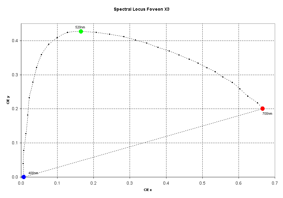
This chart also shows the red, green, and blue dominant wavelengths as colored
circles.
Getting very small values such as those at 690nm and 700nm can be tricky.
If the Spectral Locus behaves badly then small values like these may need some
adjustment.